Effects of Electric Current
Maharashtra Board-Class 10-Science & Technology Part-1-Chapter-4
Notes
|
Topics to be learn :
|
Introduction :
Electrical conductor : A material which has very low electrical resistance is called a good conductor of electricity.
- Examples: silver, copper, aluminium.
Electricity Insulator : A material which has extremely high electrical resistance is called an insulator of electricity.
- Examples : rubber, wood, glass.
Energy transfer in electric circuit :
Electric power : Electric power is the electric work done per unit time or electric energy used per unit time. Its SI unit is the watt (W).
Electric power (P) = \(\frac{\text{electrical work (W) or electrical energy used}}{time(t)}\)
P =VI = I2R = V2/R.
Mechanical power : Similar to the electric power we can write,
Mechanical power (P) = \(\frac{\text{Mechanical work (W)}}{time(t)}\)
P = W/t = Fscos/t
The watt : If one joule of electric work is done per second, the electric power is 1watt.
1 watt (W) = 1joule (J) / 1 second (s)
Commercial unit of electric energy : The commercial unit of electric energy is the
kilowatt-hour (kW.h),
1 kW.h -3.6 x 10⁶J
It is commonly known as the unit.
The unit of electric power 1W is a very small unit, hence 1000W or 1 kW is used as a unit to measure electric power, in practice. If 1kW power is used for 1 hour, it will mean 1 kWx 1 h of electric energy is used
1KW.h= 1 kilowatt-hour = 1000W x 3600s
= 3.6 x 10⁶ w.s = 3.6 x 10⁶J
Electricity bill : Electricity bill shows the consumption of units (i.e., kWh) and the cost of using electric energy. When 1 kWh electric energy is used, it is termed as 1 unit of energy.
Heating effect of electric current :
The production of heat in a resistance due to the electric current flowing through it when it is connected in an electrical circuit, is called the heating effect of electric current.
Origin of the heating effect of electric current :
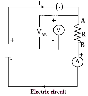
- When a potential difference is applied across a metallic conductor, free electrons in the conductor move from the end at the lower potential to the end at the higher potential giving rise to electric current.
- These electrons collide with the atoms and positive ions and transfer some kinetic energy to them. This energy is converted into heat.
- Hence, the temperature of the conductor begins to rise i.e., the conductor becomes hot. This is the origin of the heating effect of electric current.
Joule's law about heating effect of electric current: The quantity of heat produced (H) in a conductor of resistance R, when a current I flows through it for a time t is directly proportional to
- The square of the current
- The resistance of the conductor
- The time for which the current lows.
Mathematical expression for the heat generated in a metallic conductor by electric current (Joule’s law) : If Vis the potential difference applied across a metallic conductor of resistance R, the current through the conductor, given by Ohm’s law, is I = V/R. …..(1) The charge passing through the conductor in time t when the current I flows in the conductor is Q = It ….(2) The work done in this process is W = VQ …..(3) From Eqs. (1), (2) and (3), we have, W = (IR) (It) = I2Rt = VIt = \(V\frac{V}{R}t\) = \(\frac{V^2}{R}t\) This work is converted into heat. When I is expressed in ampere, R in ohm, z in second and V in volt, W is expressed in joule. In that case, _ W = I2Rt = VIt = \(\frac{V^2}{R}t\) (in joule) Usually heat energy (H) is expressed in calorie Using the relation 4.18 J = 1 cal, we have H = W = \(\frac{I^2RT}{4,18}\) cal = \(\frac{VIT}{4,18}\) cal = \(\frac{V^2T}{4,18R}\) cal This is the required expression.
Application : The working of an electric bulb, electric iron, fuse wire, etc., is based on the heating effect of electric current.
Electrical conductors having higher resistivity are used here.
Examples :
- A coil made up of an alloy Nichrome is used in the electric heater-cooker as a resistor.
- Tungsten wire is used in an electric bulb. Because of the current, this wire gets heated (to nearly 3400 0C) and emits light. The hot wire also radiates heat to a certain extent.
Fuse : A fuse protects electrical circuits and appliances by stopping the flow of electric current when it exceeds a specified value. For this, it is connected in series with the appliance (or circuit) to be protected.
- A fuse is a piece of wire made of an alloy of low melting point (e.g. an alloy of lead and tin). If a current larger than the specified value flows through the fuse, its temperature increases enough to melt it. Hence, the circuit breaks and the appliance is protected from damage.
Know This :
|
Short circuiting :
- When a bare live wire (phase wire) and a bare neutral wire come into direct contact or are very close to each other, the resistance of the circuit becomes very small and hence a large (very high) electric current flows through it. This is referred to as a short circuit or short circuiting
- In this case, a large amount of heat is produced and the temperature of the components involved becomes very high. Hence, the circuit catches fire.
Overloading : A flow of large amount of current in a circuit, beyond the permissible value of current, is called overloading.
- It occurs when many electrical appliances of high power rating, such as a geyser, a heater, an oven, a motor, etc., are switched on simultaneously. This causes fire.
- Overloading can be avoided by not connecting many electrical appliances of high power rating in the same circuit.
Magnetic effect of electric current :
Passage of electric current through a conductor also produces a magnetic field around it. This effect called magnetic effect of electric current, was discovered by Hans Christian Oersted. The unit of intensity of magnetic field, the oersted, is named after him.
Intensity Magnetic field due to a current-carrying conductor :
- The intensity of the magnetic field produced at a given point is directly proportional to the current passing through the conductor.
- The intensity of the magnetic field produced by a given current in the conductor decreases as the distance from the conductor increases.
Observation of Oersted’s experiment : Conclusion :
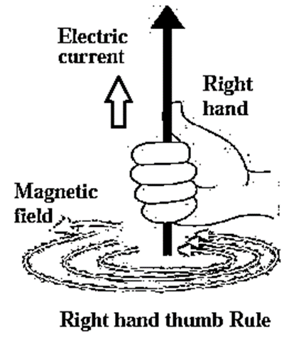
Right hand thumb rule : Imagine that you have held a current—carrying straight conductor in your right hand in such a way that your thumb points in the direction of the current. Then turn your fingers around the conductor. The direction of the fingers is the direction of the magnetic lines of force produced by the current.
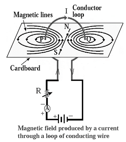
Magnetic field due to a current through a circular loop of a conducting wire :
- The intensity of the magnetic field due to a current through a circular loop of a conducting wire is maximum at the centre of the loop.
- In the case of a circular coil, the magnetic field is proportional to the number of turns of the coil, i.e., if there are n turns in the loop, the magnetic field produced will be n times that produced by a single loop.
Magnetic field due to a current in a solenoid :
Solenoid : When a copper wire with a resistive coating is wound in a chain of loops (like a spring), it is called a solenoid.
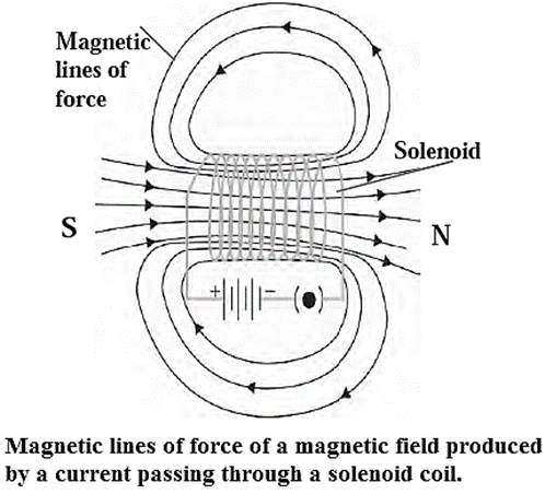
Magnetic field due to a current in a solenoid : The magnetic field lines due to a current in a solenoid are similar to those in the case of a bar magnet. A current-carrying solenoid behaves like a bar magnet and with it we can magnetise iron and some alloys.
Force on a current-carrying conductor in a magnetic field :
- A current-carrying conductor is acted upon by a (magnetic) force when placed in a magnetic field.
- The magnitude of this force depends on the current, the magnetic field, the length of the conductor (assumed to be straight) and the angle between the directions of the current and the field.
- The direction of the force depends on the directions of the current and the field.
- The force is maximum when the direction of the current is at right angles to the direction of the magnetic field.
- The force is zero when the current and the field have the same direction or opposite directions.
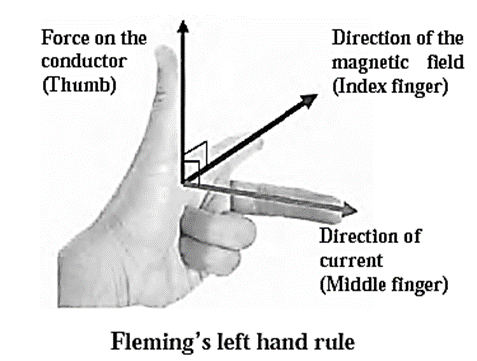
Flenling's left hand rule : The left hand thumb, index finger, and the middle finger are stretched so as to be perpendicular to each other. If the index finger is in the direction of the magnetic field, and the middle finger points in the direction of the current, then the direction of the thumb is the direction of the force on the conductor.
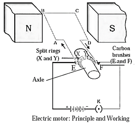
Electric motor : An electric motor is a device that converts electric energy into mechanical energy. It operates on the principle that a current carrying conductor in a magnetic field experiences a force.
Construction of an electric motor : Below figure shows the construction of an electric motor. Working :
Uses of an electric motor : An electric motor is used in a mixer, a blender, a refrigerator, a washing machine, an electric fan, a tape recorder, a hair dryer, a record player. a blower, an electric car, a rolling mill, an electric crane, an electric lift, an electric train, a computer, a pump, etc.
Electromagnetic induction :
Electromagnetic induction :The process by which a changing magnetic field in a conductor induces a current in another conductor is called electromagnetic induction.
- A current can be induced in a conductor either by moving it in a magnetic field or by changing the magnetic field around the conductor.
- Electromagnetic induction was discovered by Michael Faraday (in 1831) and independently by Joseph Henry (in 1830),
Galvanometer :
A galvanometer is a sensitive instrument used to detect the presence of current in a circuit.
- It can also be used for some electrical measurements.
- The deflection of its pointer is usually proportional to the current.
- The deflection is on either side of the zero mark at the centre of the scale depending on the direction of the current.
A galvanometer can be modified suitably to measure
- current as in an ammeter
- potential difference as in a voltmeter.
Faraday's law of induction :
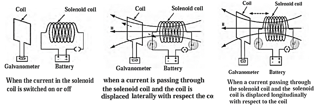
Whenever the number of magnetic lines of force passing through a coil changes, a current is induced in the coil. The current produced in the coil is called the induced current.
Fleming's right hand rule :
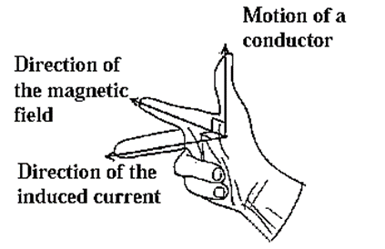
Stretch the thumb, the index finger and the middle finger of the right hand in such a way that they are perpendicular to each other. In this position, the thumb indicates the direction of the motion of the conductor, the index finger the direction of the magnetic field and the middle finger shows the direction of the induced current.
Alternating current (AC) and Direct Current (DC)
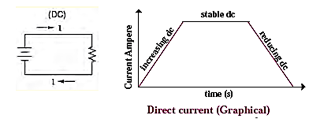
Direct current (DC) :A non oscillatory current that flows only in one direction is called a direct current (DC).
- It can change in magnitude, but its direction remains the same.
- A direct current is used in a portable electric torch and radio, in an electric bell, a wall clock, to prepare an electromagnet, for electrolysis, etc.
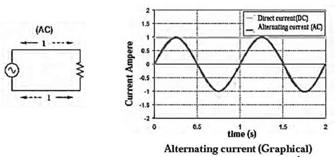
Alternating current (AC) : A current that changes in magnitude and direction after equal intervals of time is called an alternating current (AC).
- Electric current changes sinusoidally with time Electric current and potential difference are Shown by the symbol ~.
- In India, ‘the value of frequency of AC is 50 hertz.
- One advantage of AC over DC is that electric power can be transmitted over long distances without much loss of energy.
- An alternating current is used in an electric heater and a refrigerator, in an electric iron, a washing machine, an electric mixer, a food processor, an air-conditioner, an electric fan, etc.
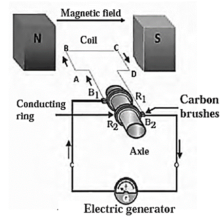
Electric generator : An electric device which converts mechanical energy into electric energy is called an electric generator.
- Its working is based on electromagnetic induction.
- When the coil of an electric generator rotates in a magnetic field, a current is induced in the coil. This induced current then flows in the circuit connected to the coil.
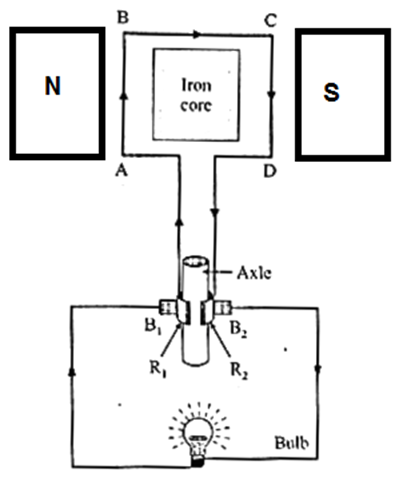
- A generator producing a direct current is called a DC generator and that producing an alternating current is called an AC generator.
Construction and working of an electric generator (AC) : Construction : Below fig shows a copper wire coil ABCD, kept between the two pole pieces of a magnet. Working :
Construction and working of an electric generator (DC) : Below figure shows the construction of DC generator. Working :
Useful links :
| Main Page : - Maharashtra Board Class 10 Science & Technology Part-1 - All chapters notes, solutions, videos, test, pdf.
Books : MSBSHSE -Class 10th Science Text Books – Chapter wise PDF for download Previous Chapter : Chapter-3-Chemical reactions and equations - Online Notes Next Chapter : Chapter-5-Heat - Online Notes |
Nice information thanks
Good notes 👍🏼
10th note give science