Solution
Question 1:
Tell the odd one out. Give proper explanation.
1. Fuse wire, bad conductor, rubber gloves, generator.
2. Voltmeter, Ammeter, galvanometer, thermometer.
3. Loud speaker, microphone, electric motor, magnet.
(1) Generator. (It converts mechanical energy into electric energy, the remaining three do not.) (2) Thermometer. (It measures temperature, the remaining three measure electrical quantities.) (3) Magnet. (It attracts/ repels magnetic materials, the remaining three convert one form of energy into another.)
Question 2:
Explain the construction and working of the following. Draw a neat diagram and label it.
1. Electric motor
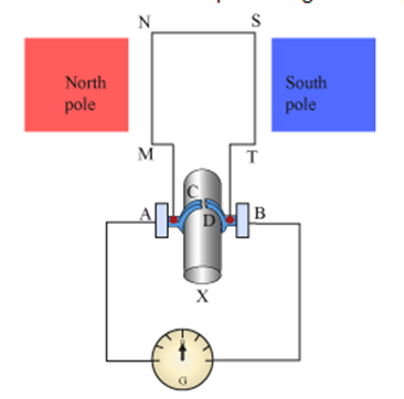
Motor principle: The basic principle on which the electric motor works is the magnetic effect of current. A current carrying rectangular coil starts rotating when placed in a magnetic field. Construction : Working : (1) When the circuit is completed with a plug key or switch, the current flows in the direction A-M-N-S-T-B. As the magnetic field is directed from the north pole to the south pole, the force on MN is downward and that on ST is upward by Fleming's left hand rule. Hence, MN moves downward and ST upward. These forces are equal in magnitude and opposite in direction.
Figure shows the construction of an electric motor. Here, rectangular loop MNST of
copper wire with resistive coating is placed between the north pole and south pole of a strong magnet, such as a horseshoe magnet, such that the branches MN and ST are perpendicular to the direction of the magnetic field. The ends of the loop are connected to the two halves, C and D, of split rings-C and d have resistive coating on their inner surfaces and are tightly fitted on the axle. The outer conducting surfaces of C and D are in contact with two stationary carbon brushes, A and B, respectively.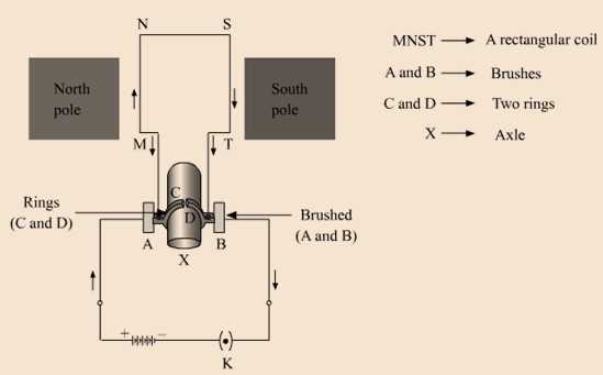
Therefore, as observed from the side MT, the loop MNST and the axle start rotating in anticlockwise direction.
(2) After half a rotation, C and D come in contact with brushes A and B respectively and the current flows in the direction ATSNMB. Hence the force on ST is downward and that on MN is upward. Therefore, the loop and the axle continue to rotate in the anticlockwise direction.
(3) After every half rotation, the current in the loop is reversed and the loop and the axle continue to rotate in anticlockwise direction. When the current is switched off, the loop stops rotating after some time.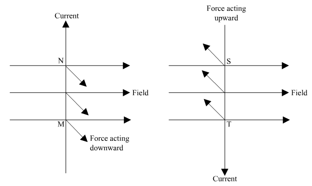
2. Electric Generator (AC)
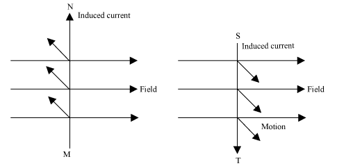
Electric Generator principle : An electric generator is a machine that generates electricity by rotating its rotor in a magnetic field. Thus, it converts mechanical energy into electrical energy. Construction: A generator consists of a rectangular coil MNST of insulated copper wire placed between two strong magnetic poles. The two ends of the coil MNST are connected with brushes A and B of rings C and D respectively. The inner sides of the rings are insulated. They are attached with an axle X, which can be rotated mechanically. Brushes A and B are connected with a galvanometer that can measure the flow of current in coil MNST. Working: When the axle is rotated, lengths MN and ST move up and down respectively. Since lengths MN and ST are moving in a magnetic field, a current gets induced in these lengths caused by an electromagnetic induction. The direction of the induced current in both the lengths is given by Fleming’s right hand rule. Since length MN is moving upwards in the magnetic field that acts from left to right, the direction of the induced current will be from M to N. Similarly, the direction of the induced current in length ST will be from S to T. Hence, an induced current will set up in the coil in the direction MNST, which produces deflection in the galvanometer. The direction of the induced current in the coil gets reversed i.e. the induced current will now flow from T to M via S and N i.e. TSNM. Therefore, we can conclude that after each half-rotation, the direction of the induced current is reversed. This current is called an alternating current (AC). An AC reverses its direction after equal time intervals.
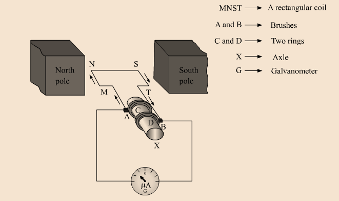
After half-rotation, length MN starts moving down, whereas length ST starts moving up.
Question 3:
Electromagnetic induction means-
a. Charging of an electric conductor.
b. Production of magnetic field due to a current flowing through a coil.
c. Generation of a current in a coil due to relative motion between the coil and the magnet.
d. Motion of the coil around the axle in an electric motor.
Electromagnetic induction means generation of a current in a coil due to relative motion between the coil and the magnet.
Question 4:
Explain the difference:
AC generator and DC generator.
AC generator
DC generator
i.
The directions of current produced reverses after equal intervals.
The current produced flowin the same direction all the time.
ii.
It has two simple ring-type commutators.
It has a single split-ring commutator.
Question 5:
Which device is used to produce electricity? Describe with a neat diagram.
a. Electric motor
b. Galvanometer
c. Electric Generator (DC)
d. Voltmeter
The device used for producing electricity is Electric generator (DC). It is based on the phenomenon of electromagnetic induction. Working: When the axle is rotated, lengths MN and ST move up and down, respectively. Since lengths MN and ST are moving in a magnetic field, a current gets induced in these lengths caused by an electromagnetic induction. The direction of the induced current in both the lengths is given by Fleming’s right hand rule. Here, split rings C and D act as a commutator. In this case, the direction of the current induced in the coil will be from M to T via N and S for the first half-rotation, and from T to M via S and N for the second half-rotation of coil MNST. Hence, we get a unidirectional current called direct current (DC).
In this arrangement, brush A always remains in contact with the length moving up, whereas brush B always remains in contact with the length moving down.
Question 6:
How does the short circuit form? What is its effect?
Short circuit occurs when naked live and neutral wires touch each other. Thus, the decrease in value of resistance of the circuit raises the current to a significant amount. As a result, the wires become hot and sparks are caused by Joule’s heating effect of current.
In such situations, the resistance of the circuit becomes very less. Now, according to Ohm’s law, current is inversely proportional to resistance.
Question 7:
Give scientific reasons. Tungsten metal is used to make a solenoid type coil in an electric bulb because its melting point is very high. Thus, when a high amount of current is passed through it, it becomes red hot and emit lights without getting burnt.
1. Tungsten metal is used to make a solenoid type coil in an electric bulb.
2. In the electric equipment producing heat e.g. iron, electric heater, boiler, toaster etc, an alloy such as Nichrome is used, not pure metals. In the electric equipment producing heat, such as iron, electric heater, boiler, toaster etc., an alloy such as Nichrome is used, not pure metals because of the following reasons:
(i) Resistivity of Nichrome is more compared to pure metal.
(ii) Melting point of Nichrome is high as compared to pure metal.
(iii) Nichrome does not get oxidised when heated in air whereas metal does.
3. For electric power transmission, copper or aluminium wire is used.
For electric power transmission, Copper or Aluminium wire is used because they provide low resistance path to the flow of current. Thus, the power loss in the low resistance transmission wire will be less.
4. In practice the unit kWh is used for the measurement of electrical energy, rather than joule.
In practice, the unit kWh is used for the measurement of electrical energy, rather than joule. This is because joule is a very small unit and the energy consumption in day to day life is very large i.e. it comes in figures of 106 to 108. Thus, to reduce the complexity of handling such large figures, a bigger unit was required. This bigger unit used for the measurement of electrical energy is kWh and is related to joule as
1 kWh = 3.6 × 10⁶ J
Hence, in practice the unit KW.h is used for the measurement of electric energy instead of joule.
Question 8:
Which of the statement given below correctly describes the magnetic field near a long, straight current carrying conductor?
a. The magnetic lines of force are in a plane, perpendicular to the conductor in the form of straight lines.
b. The magnetic lines of force are parallel to the conductor on all the sides of conductor.
c. The magnetic lines of force are perpendicular to the conductor going radially outword.
d. The magnetic lines of force are in concentric circles with the wire as the center, in a plane perpendicular to the conductor.
The correct statement describing the magnetic field near a long, straight current carrying conductor is:
The magnetic lines of force are in concentric circles with the wire as the center, in a plane perpendicular to the conductor.
Question 9:
What is a solenoid? Compare the magnetic field produced by a solenoid with the magnetic field of a bar magnet. Draw neat figures and name various components.
A solenoid is a long straight insulated wire, such as a copper coil, often wrapped around a cylinder-shaped body. The diameter of the solenoid is lesser than its length. It produces a magnetic field when electric current is passed through it. On comparing field lines produced by a solenoid with that produced by a bar magnet, we observe that they are very much identical. Thus, a solenoid acts as a bar magnet when current is passed through it.
Magnetic field produced by a solenoid and by bar is shown below: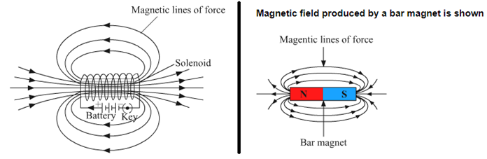
Question 10:
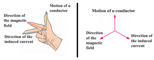
Name the following diagrams and explain the concept behind them.
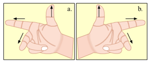
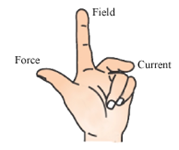
a. It represents Fleming's right hand ruleused for finding the direction of induced current with respect to the directions of the magnetic field and motion of the conductor. The direction of current induced in a conductor can be obtained by holding the thumb, the index finger, and the middle finger of your right hand mutually perpendicular to each other. In this situation, the thumb indicates the direction of the motion of the conductor, the index finger points along the magnetic field, and the middle finger points along the current induced in the conductor. b. It represents Fleming's left hand rule used for finding the direction of magnetic force when a current carrying conductor is placed in a magnetic field. This rule states that if you stretch the thumb, index finger, and middle finger of your left hand such that they are mutually perpendicular to each other, then your index finger represents the direction of the field, the middle finger represents the direction of the current, and the thumb represents the direction of the force experienced by the conductor.
Question 11:
Identify the figures and explain their use.
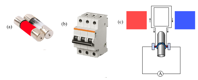
Figure (a) - fuse. An electric fuse is a safety device that protects the wiring against excessive heating caused by an excess supply of current. It melts when heavy current flows through the circuit, thereby causing the circuit to become open. Figure (b) - MCB. An MCB is a device which functions as a fuse, but does not require replacement. MCB falls down to break the circuit when heavy amount of current flows through it. Once the fault is rectified, the MCB is reset. Figure (c) - DC generator. It is a device that generates electricity by rotating its rotor in a magnetic field. Thus, it converts mechanical energy into electrical energy
Question 12:
Solve the following example.
1. Heat energy is being produced in a resistance in a circuit at the rate of 100 W. The current of 3 A is flowing in the circuit. What must be the value of the resistance?
Given: R= \(\frac{P}{I^2}\) = 100/9 = nearly 11 Ω
Power, P =100 W
Current, I = 3 A
Resistance, R = ?
We know, P = \(I^2R\)
2. Two tungsten bulbs of wattage 100 W and 60 W power work on 220 V potential difference. If they are connected in parallel, how much current will flow in the main conductor?
Power of first bulb, P1 = 100 W Resistance of first bulb, R2=V2/P2 =(220x220)/60 = 806.7 Ω (Standard Volt V=220V) When the bulbs are connected in parallel, their equivalent resistance is Req = \(\frac{R_1×R_2}{R_1+R_2} = \frac{484 ×806.7}{484 +806.7}\) = 302.5 Ω Current flowing in the main conductor is I= V/Req = 220/302.5 ≅ 0.72 A
Power of second bulb, P2 = 60 W
Now,
Resistance of first bulb, R1=V2/P1 =(220x220)/100 = 484 Ω (Standard Volt V=220V)
3. Who will spend more electrical energy? 500 W TV Set in 30 mins, or 600 W heater in 20 mins?
We know,
Electrical energy (E) =Power (P)×Time (t)Electrical energy (E) =Power (P)×Time (t)
For TV set,
E = 500×30×60=900000 J
For heater,
E = 600×20×60=720000 J
Thus, TV set consumes more electrical energy.
4. An electric iron of 1100 W is operated for 2 hrs daily. What will be the electrical consumption expenses for that in the month of April? (The electric company charges Rs 5 per unit of energy).
Electric power required for working of iron, P = 1100 W N=\(\frac{Pt}{1000(W.h/unit)} =\frac{1100W×60h}{1000(W.h/unit)}\) = 66 units Cost of 1 unit of energy = Rs 5
Duration for which the iron is operated daily = 2 h = 2×30= 60h
Electric energy consumed by iron in unit is
Thus, total electrical consumption expenses for the month of April = 66×5 = Rs 330