Notes
Topics to be learn :
- Potential and potential difference
- Electric current
- Electric circuit
- Symbols for components of an electric circuit and uses of the components
- Resistance and Ohm’s law
- Resistivity
- Resistors in series
- Resistors in parallel
- Fuse wire
- Domestic electrical connections
- Precautions to be taken while using electricity
Electric potential : The electric level at a point is called the electric potential at that point. Its SI unit is the volt (V).
Potential difference : The potential difference between two points in an electric field is the amount of work done to carry a unit positive charge from one point to other point. Its SI unit is the volt.
Potential difference, V = \(\frac{work(W)}{charge(Q)}\)
The volt : The potential difference between two points is said to be 1 volt if 1 joule of work is done in moving 1 coulomb of electric charge from one point to another.
1 volt = \(\frac{1\,joule(J)}{1\,coulomb(C)}\)
(1) The units millivolt and microvolt are used for small voltages.
1 millivo1t= 10-3 volt or 1 mV = 10-3 V,
1 microvolt = 10-6 volt or 1 mV = 10-6 V
(2) The units kilovolt and megavolt are used for large voltages.
1 kilovolt = 103 volts or 1 kV = 103 V,
1 megavolt = 106 volts or 1 MV = 106 V.
Free electrons : Every atom of a metallic conductor has one or more outermost electrons which are very weakly bound to the nucleus. These are called free electrons.
Electric current :
(i) Electric current is a flow of electrons in a conductor or amount of charge flowing through a particular cross sectional area in unit time.
- Electric current, I =Q/t where Q is the net charge flowing through any cross section of a conductor in time t.
(ii) Even though electrons move from negative end to positive end, conventionally, the direction of current flow is taken to be opposite of the direction of flow of electrons i.e. from the + ve end to the — ve end of a cell.
(iii) Very small values of current are expressed in the following units.
- 1 mA (milliampere) = 10-3 A
- 1 mA (microampere) = 10-6 A
The ampere : The SI unit of electric current is the ampere (A). If one coulomb of charge is passing through any cross section of a conductor in one second, the amount of current flowing through it is called one ampere.
1 ampere (A) = \(\frac{1\,coulomb(C)}{1\,second(s)}\)
The current flow in a metal wire(or a metallic conductor:
- In a metal wire (metallic conductor), each atom has one or more than one electrons in the outermost orbit which are very weakly attracted by the nucleus.
- These loosely bound electrons are almost free, i.e., they can move from atom to atom in the wire (conductor). But these electrons do not escape from the metal surface.
- If the metal wire is not connected to a cell or a battery, the ‘free’ electrons, like gas molecules, move at random within the wire.
- Hence, there is no net transfer of electric charge in any direction.

- The positive metal ions, however, being very massive relative to electrons, do not move like free electrons. They simply vibrate about their mean positions.
- Suppose that a cell (source of electricity) is connected across the wire. Then an electric force acts on all charges in the wire.
- This causes a net flow of electrons (negative charges) through the wire from the negative end to the positive end of the cell.
- This flow is the electric current. The electrons, accelerated by the electric force, acquire greater velocity. But they collide with the positive ions and transfer some kinetic energy to them.
- On an average, these electrons move with a certain speed called the average drift speed which depends on the electric force and other factors.
- Ordinarily, when electric current is small, this speed is very small, about 1 mm per second.
Thus, the electric current in a metal wire is due to the net flow of ‘free’ electrons under the action of the electric force due to a source of electricity like a cell.
Electric circuit : A continuous path consisting of conducting wires, a switch or a plug key and other resistances (e.g., resistance of an appliance, electric bulb, electric fuse, etc.) between the terminals of a battery (or a cell) along which an electric current flows is called an electric circuit.

Circuit diagram : A diagram which indicates how different components in a circuit are connected, using the electrical symbols for the components, is called a circuit diagram.
Advantage of a circuit diagram : If connections are made using a correct circuit diagram, the chances of making wrong connections are reduced. Circuit digram also useful for troubleshooting the electrical fault in machinery and maintenance of electrical and electronic equipment..
Resistance : The property of a conductor due to which it opposes a flow of (electric) current through it is called (electric) resistance and it is numerically equal to the ratio of the (electric) potential difference across its ends to the current flowing through it. Its SI unit is the ohm (denoted by Ω).
- Resistance, R = potential difference (V)/current (I)
Conductor : A substance which has very low electrical resistance is called a conductor.
- Example : Silver, copper and aluminium are good conductors.
Insulators : A substance which has extremely high electrical resistance is called an insulator.
- Example :Rubber, wood and glass are good insulators.
| A substance that contains almost free charges normally electrons is a conductor.
A substance that does not contain free charges is an insulator. Our body contains nearly free positive and negative charges. Hence it can conduct electricity. |
Semiconductor : A substance which behaves as an insulator under normal conditions, but behaves as a conductor under certain conditions is called a semiconductor. Germanium and silicon are semiconductors.
Super conductor and unohmic conductor: Even if any one of the several bulbs connected in parallel becomes non-functional because of some damage to its filament, the circuit does not break as the current flows through the other paths, and the rest of the bulbs light up.
When several bulbs are connected in parallel, they emit the same amount of light as when they are connected individually in the circuit, while bulbs connected in series emit less light than when connected individually.
0hm’s law : The electric current flowing in a conductor is directly proportional to the potential difference across its terminals, provided the physical conditions of the conductor such as its length, area of cross section, temperature and material remain constant.
The ohm : If one ampere current flows through a conductor when 1 volt potential difference is applied across it, its resistance is one ohm.
1 ohm (W) = 1 volt (V)/1 ampere (A)
Resistivity: The resistance of a conductor of length L and area of cross section A is R = where r is the resistivity of the conductor. r depends on the material and temperature, but not on the length and the area of cross section of the conductor For unit length and unit area of cross section, r = R.
The resistivity of a conductor is the resistance of a conductor of unit length and unit area of cross section.
Its SI unit is the ohm-metre (Ω-m),
The resistance of a wire, R = \(ρ\frac{L}{A}=ρ\frac{L}{πR^2}\)
Where r = radius of the wire.
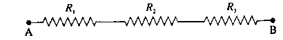
Resistors in series : The effective resistance of a series combination of n resistors with resistances R1,R2, ...,Rn, is RS = R1 + R2 +…… + Rn,.
In this case, when a potential difference is applied across the combination, the current through each resistor is the same.
Resistors in parallel : The effective resistance of a parallel combination of n resistors with resistances R1, R2,…. Rn is denoted by RP and is given by
\(\frac{1}{R_p}=\frac{1}{R_1}+\frac{1}{R_2}+.......\frac{1}{R_n}\)
In this case, the potential difference across each resistor is the same as that across the combination.
| The resistance of some conductors becomes nearly zero if their temperature is decreased up to a certain value close to 0 K. Such conductors are called super conductors.
Some conductors do not obey Qhm's law Such conductors are called nonohmic conductors, |
Expression for the effective resistance when a number of resistors are connected in series :
Figure shows the circuit diagram for a series combination of three resistors with resistances R1, R2 and R3 connected between points C and D.

The ammeter in the circuit measures the (total) current I while the voltmeter measures the potential difference across a resistor.
We assume that the ammeter has very low resistance and the voltmeter has very high resistance so that these meters do not change significantly the quantities being measured.
Let V=potential difference (P.D.) between C and D,
V1, V2, and V3 =P.D. across the resistor with resistance R1, the resistor with resistance R2 and the resistor with resistance R3 respectively.
Then,
V= V1+ V2 + V3 ………….(1)
Let RS = effective (or equivalent or resultant) resistance of the series combination. As the same current I flows through each resistor, we have, by
Ohm’s law.
V = IRS and V1 = IR1, V2= IR2, V3 = IR3
Combining these equations with Eq. (1). we get.
IRS = IR1 + IR2 + IR3
\ RS = R1 + R2 + R3 …….(2)
If n resistors of resistances R1, R2, Rn, are connected in series, the effective (or equivalent or resultant) resistance of the combination is
RS = R1 + R2 +….+ Rn
Characteristics of a series combination of resistors :
- The same current flows through each resistor.
- The voltage (potential difference) across the combination is equal to the sum of the voltage drops across the individual resistors.
- The effective resistance of the combination is equal to the sum of the individual resistances.
- The effective resistance of the combination is greater than any of the individual resistances.
- The voltage across each resistor is directly proportional to the resistance of the resistor.
- This combination can be used to increase the resistance in a circuit.
Q. Obtain an expression for the effective resistance when a number of resistors are connected in parallel.
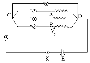
Figure shows the circuit diagram for a parallel combination of three resistors with resistances R1, R2 and R3 connected between points C and D.

The voltmeter measures the potential difference V between C and D and the ammeter measures the current in a given branch.
We assume that the ammeter has very low resistance and the voltmeter has very high resistance so that those meters do not change significantly the quantities being measured.
Let I = total current in the circuit.
I1= current through the resistor with resistance R1
I2 = current through the resistor with resistance R2, and
I3 = current through the resistor with resistance R3.
Then
I = I1 + I2 + I3 ...(1)
If RP is the effective (or equivalent or resultant) resistance of the parallel combination, we have, by
Ohm's law.
\(I= \frac{V}{R_p}\) and \(I_1= \frac{V}{R_1}\), \(I_2= \frac{V}{R_2}\), \(I_3= \frac{V}{R_3}\)
Combining these equations with Eq. (1), we get,
\(\frac{V}{R_p} = \frac{V}{R_1}+ \frac{V}{R_2}+ \frac{V}{R_3}\)
∴\(\frac{1}{R_p} = \frac{1}{R_1}+ \frac{1}{R_2}+ \frac{1}{R_3}\) .......(2)
If n resistors with resistances R1, R2,… Rn, are connected in parallel between two common points, the effective (or equivalent or resultant) resistance,
RP, of the combination is given by
\(\frac{1}{R_p} = \frac{1}{R_1}+ \frac{1}{R_2}+.... \frac{1}{R_n}\)
Characteristics of a parallel combination of resistors :
- The voltage (potential difference) across each of the resistors is the same.
- The total current is equal to the sum of the currents through the individual resistors.
- The reciprocal of the effective resistance of the combination is equal to the sum of the reciprocals of the individual resistances.
- The effective resistance of the combination is less than any of the individual resistances.
- The current through each resistor is inversely proportional to the resistance of the resistor.
- This combination can he used to decrease the resistance in a circuit
Advantages of Electrical appliances connected in parallel :
In the parallel arrangement of electric appliances, the applied potential difference is the same in each case. Further, even if one of the appliances does not work or is removed for repairing, the other appliances can still be used.
Difference between Resistances in series and Resistances in parallel.
| Resistances in series | Resistances in parallel |
| 1-Current is the same in every part of the circuit.
2-The equivalent resistance of the combination is equal to the sum of the individual resistances. 3-The equivalent (effective) resistance is greater than any of the individual resistances. 4-Series combination is used to increase the resistance in the circuit. |
1-Voltage is the same across every resistor.
2-The reciprocal of the equivalent resistance of the combination is equal to the sum of the reciprocals of the individual resistances. 3-The equivalent (effective) resistance is less than any of the individual resistances. 4- Parallel combination is used to decrease the resistance in the circuit. |
Q. If two bulbs are connected in series instead of parallel, what will happen if the filament of one of the bulbs breaks?
If two bulbs are connected in series instead of parallel, if the filament of one of the bulbs breaks, there will be no current through the other bulb as well even if the circuit is switched on. Hence the other bulb will also not glow.
Q.Two dissimilar bulbs are connected in series. Which bulb will be brighter?
(Hint : Consider the resistance of the bulb.)
The bulb of higher resistance will be brighter, assuming that the filaments of the two bulbs have the same length and the same area of cross section, but are made of metals with different resistivities.
Explanation : Heat generated (H) in time t = I2Rt , where I is the current through a conductor and R is the resistance of the conductor.
In a series combination, the current through each conductor is the same.
H ∝ R for a given t.
Hence, the bulb with higher R will become more hot and hence emit more light energy per second.
Introduction to Scientist :
(1) The Italian scientist Alessandro Volta constructed the first electric cell. The unit of potential difference is ‘volt’ in his honour.
(2) The French mathematician and scientist, Ampere, conducted a number of experiments on electricity. Today, we can measure the current flowing in a conductor only because of his extraordinary work. The unit of current is called ampere in recognition of his great work.
(3) German physicist, Georg Simon Ohm, established a law for measuring the resistance of a conductor. In his honour, the unit of resistance is called the ohm.
Safety :
Fuse wire : Fuse wire is used to protect domestic appliances.
- It is made of a mixture of substances and has a specific melting point.
- It is connected in series to the electric appliances.
- If for some reason, the current in the circuit increases excessively, the fuse wire gets heated up and melts. The circuit gets broken and the flow of current stops, thus protecting the appliance.
- This wire is fitted in a groove in a body of porcelain-like non-conducting material. For domestic use, fuse wire with upper limits of 1 A, 2 A, 3 A, 4 A, 5 A and 10 A are used.

Rubber gloves and rubber soled shoes should be used while working with electrical appliances.
Symbols for components of an electric circuit and their uses :
1) Electric cell: To apply a potential difference between two ends of a conductor.
![]()
Picture & Symbol
2) Battery (collection of a number of cells) : To apply a larger potential difference between two ends of a conductor
![]()
Picture & Symbol
3) Open tap key or plug key : To stop the flow of current flowing in a circuit by disconnecting two ends of a wire.
![]()
Picture & Symbol
4) Closed tap key or plug key : To start the flow of current in a circuit by connecting two ends of a wires.
![]()
Picture & Symbol
5) Connecting (conducting) wires : To connect various components in the circuit.
![]()
Picture & Symbol
6) Crossing wires : To show wires which cross but are not connected.

Picture & Symbol
7) Light bulb : To test the flow of electricity :
- Lighted : current is flowing;
- Unlighted : current is not flowing
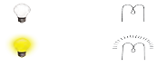
Picture & Symbol
8) Resistance : To control the flow of current in the circuit.
![]()
Picture & Symbol
9) Variable resistance : To change the resistance as required and thereby control the current
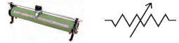
Picture & Symbol
10) Ammeter : To measure the current flowing in the circuit.

Picture & Symbol
11) Voltmeter : To measure the potential difference between two points in the circuit.

Picture & Symbol
Domestic electrical connections : The electricity in our homes is brought through the main conducting cable either from the electric pole or from underground cables.
- Usually, there are three wires in the cable.
- One is called the live wire which brings in the current. It has a red or brown insulation.
- The other wire is called neutral wire through which the current returns. It is blue or black.
- In India, the voltage difference between the live and neutral wires is about 220 V. Both these wires are connected to the electric meter tough a fuse.
- Through a main switch, they are connected to all the conducting wires inside the home so as to provide electricity to every room.
- In each separate circuit, various electrical appliances are connected between the live and neutral wires.
- The different appliances are connected in parallel and the potential difference across every appliance is the same.
- The third wire is called the earth wire and is of yellow or green colour. This is connected to a metal plate buried deep underground near the house and is for safety purposes.
Precautions to be taken while using electricity :
- Electric switches and sockets should be fitted at a height at which small children cannot reach and put pins or nails inside. Plug wires should not be pulled while removing electrical plug from its socket.
- Before cleaning an electrical appliance, it should be switched off and its plug removed from the socket.
- One’s hands should be dry while handling an electrical appliance, and as far as possible, one should use footwear with rubber soles. As rubber is an insulator, it prevents the current from flowing through our body, thereby protecting it.
- If a person gets an electric shock, you should not touch that person. You should switch off the main switch and if the switch is too far or you do not know where it is located, then you should remove the plug from the socket if possible. If not, then you should use a wooden pole to push the person away from the electric wire.
Heating effect of electric current and its origin : The production of heat in a metallic conductor by the electric current through it is called the heating effect of electric current.
- When a potential difference is applied across a metallic conductor, free electrons in the conductor move from the end at the lower potential to the end at the higher potential giving rise to electric current.
- These electrons collide with the atoms and positive ions and transfer some kinetic energy to them.
- This energy is converted into heat.
- Hence, the temperature of the conductor begins to rise, i.e., the conductor becomes hot.
This is the origin of the heating effect of electric current.
Joule’s law : The quantity of heat (H) generated in a conductor of resistance R, when a current I flows through it for a time t is directly proportional to
- the square of the current
- the resistance of the conductor
- the time for which the current flows.
H = I2Rt = VIt = \(\frac{V^2}{R}t\) in joule
Usually heat energy (H) is expressed in calorie. Using the relation 4.18 J = 1 cal,
we have
H = \(\frac{I^2Rt}{4.18}\) in cal = \(\frac{VIt}{4.18}\) = \(\frac{V^2t}{4.18R}\) in cal
Here, V= IR is the potential difference across the resistor.
| The fuse wire is usually enclosed in a cartridge of an insulator such as glass or porcelain provided with metal caps. The current rating (such as 1A, 2A) may be printed on the cartridge |
Applications of heating effect of electric current
Domestic appliances based on the heating effect of electric current :
(1) Electric heater (2) electric iron (3) electric oven (4) electric toaster (5) electric kettle (6) electric geyser (7) fuse.
Some other applications of heating effect of electric current: (1) electric bulb (2) electric furnace (3) in industry for soldering, welding, cutting, drilling (4) in surgery for cutting tissues with a finely heated platinum wire.
Application of heating effect of electric current in an electric bulb
In an electric bulb, there is a filament of metal such as tungsten having high melting point (3380°C). When an electric current is passed through the filament, it becomes hot and emits light. The bulbs are usually filled with chemically inactive gases such as nitrogen and argon to prevent oxidation of the filament and hence prolong their life.
Application of heating effect of electric current in an electric iron :
In an electric iron, a coil of high resistance is held between mica sheets and placed inside a heavy metal block provided with a handle made of an insulator such as plastic. When an electric current is passed through the coil, it becomes hot. Mica is a good conductor of heat. Hence, heat generated in the coil is transferred to the metal block which can then be used for ironing clothes.
Mica is a bad conductor of electricity. Hence, there is no electrical contact between the coil and the metal block. Therefore, the person using the iron does not get an electric shock even if he or she happens to touch it by chance.
Application of heating effect of electric current in a fuse :
A fuse protects electrical circuits and appliances by stopping the flow of electric current when it exceeds a specified value. For this, it is connected in series with the appliance (or circuit) to be protected. A fuse is a piece of wire made of an alloy of low melting point (e.g. an alloy of lead and tin). If a current greater than the specified value flows through the fuse, its temperature increases enough to melt it. Hence, the circuit breaks and the appliance is protected from damage.
Earthing and its importance : The system of connecting the metal casing of an electrical appliance to a copper plate buried deep inside the earth is called earthing.
- Many appliances such as an electric heater, a toaster, an oven, a refrigerator, etc., have a metallic body (casing).
- If with use the insulation of a wire breaks or melts, the live wire may touch the metal casing. If we happen to touch the casing carrying a current, we may receive a severe shock which may cause death.
- To avoid this, metal casings of all electrical appliances are earthed.
- One end of a thick copper wire is connected to the metal casing of the appliance and the other end is connected to a copper plate buried deep inside the earth.
- The current through the metal casing then flows to the earth and the person touching the casing is saved.
Short circuit : If a bare live wire (phase wire) and a bare neutral wire touch each other (come in direct contact) or come very close to each other, the resistance of the circuit becomes very small and hence huge (very high) electric current flows through it. This condition is called a short circuit or short circuiting.
In this case, a large amount of heat is produced and the temperature of the components involved becomes very high. Hence, the circuit catches fire.
Overloading : A flow of large amount of current in a circuit, beyond the permissible value of current, is called overloading.
It occurs when many electrical appliances of high power rating, such as a geyser, a heater, an oven, a motor, etc., are switched on simultaneously. This causes fire.
Overloading can be avoided by not connecting many electrical appliances of high power rating in the same circuit.
Thanku sir
Thanku sair🙏🙏
Good