Solution
Question 1:
The accompanying figure shows some electrical appliances connected in a circuit in a house. Answer the following questions.

1. By which method are the appliances connected?
2. What must be the potential difference across individual appliances?
3. Will the current passing through each appliance be the same? Justify your answer.
4. Why are the domestic appliances connected in this way?
5. If the T.V. stops working, will the other appliances also stop working? Explain your answer.
1. The appliances are in parallel connection. 2. The potential difference across each appliance should be same as they are connected in parallel. 3. No, the current passing through each appliance is not same. From Ohm's law, the current flowing through each appliance is I=V/R, Since, potential difference across each appliance is same, each appliance can have different resistance and I∝1/R , therefore, the current flowing through them will be different. 4. Domestic appliance are connected in parallel because, even if one or more appliances get faulty or stops working, the working of others will remain unaffected. 5. As the appliances are connected parallel across the supply. The working of other appliances will remain unaffected even if the T.V. stops working.
Question 2:
The following figure shows the symbols for components used in the accompanying electrical circuit. Place them at proper places and complete the circuit.

Which law can you prove with the help of the above circuit?
Ohm's law I=V/R can be proved with the help of above circuit.

Question 3:
Umesh has two bulbs having resistances of 15 Ω and 30 Ω . He wants to connect them in a circuit, but if he connects them one at a time the filament gets burnt.
Answer the following.
A. Which method should he use to connect the bulbs?
B. What are the characteristics of this way of connecting the bulbs depending on the answer of A above?
C. What will be the effective resistance in the above circuit?
When Umesh connects the bulbs one at a time, the filaments of the bulbs get burnt. This means the heat energy generated in the filament is beyond what it can tolerate. Hence, we need to reduce the heat generated across the filament. Now, the heat generated in a resistor is proportional to the amount of current flowing through it. Thus, we need to reduce the current flowing through the bulbs. A. If bulbs are connected in series, the effective resistance of the circuit increases and hence current through the bulbs decreases. In this way, both the bulbs can be saved from burning. B. Following are the characteristics of series connection: C. The effective resistance of the circuit = 15 Ω + 30 Ω = 45 Ω
Question 4:
The following table shows current in Amperes and potential difference in Volts.
| V (Volts) | I (Amp) |
| 4 | 9 |
| 5 | 11.25 |
| 6 | 13.5 |
(i) Find the average resistance.
(ii) What will be the nature of the graph between the current and potential difference? (Do not draw a graph.)
(iii) Which law will the graph prove? Explain the law.
(i). From Ohm's law, we have (amp) Therefore, average resistance = (0.44+0.44+0.44)/3 =0.44 Ω (ii) The nature of the graph between the current and potential difference will be a straight line passing through origin (0,0). (iii) The graph proves Ohm's law. Ohm's law states that, under constant temperature and physical conditions, the current flowing through a conductor is always proportional to the potential difference across it i.e. V∝I or, V = RI
R=V/I
V
(volts)I
R
(ohm)
4
9
4/9=0.44
5
11.25
5/11.25=0.44
6
13.5
6/13.5=0.44
Question 5:
Match the pairs
| ‘A’ Group | ‘B’ Group |
| 1. Free electrons | a. V/ R |
| 2. Current | b. Increases the resistance in the circuit |
| 3. Resistivity | c. Weakly attached |
| 4. Resistances in series | d. VA/LI |
‘A’ Group
‘B’ Group
1. Free electrons
c. Weakly attached
2. Current
a. V/ R
3. Resistivity
d. VA/LI
4. Resistances in series
b. Increases the resistance in the circuit
Question 6:
The resistance of a conductor of length x is r. If its area of cross-section is a, what is its resistivity? What is its unit?
We know R = ρ(L/A) ∴ Resistivity of a conductor, ρ = RA / L Here, L = x, R = r and A = a Therefore, ρ = ra / x The unit of resistivity is ohm-metre (Ω-m).
Question 7:
Resistances R1 , R2 , R3 and R4 are connected as shown in the figure. S1 and S2 are two keys. Discuss the current flowing in the circuit in the following cases.
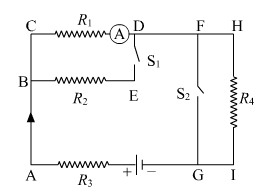
(i) Both S1and S2are closed. (i) The circuit for this case is shown below. R4 is shunted by S2 . Hence the Resistance of this combination will be practically zero R1 and R2 in parallel ∴ \(\frac{1}{R_p} = \frac{1}{R_1} + \frac{1}{R_2}\) ∴ \(R_p = \frac{R_1 R_2}{R_1 + R_2}\) R3 and Rp in series ∴ Rs = R3 + Rp ∴ I3 = \(\frac{V}{R_s}\) = \(\frac{V}{R_3 + R_p}\) V1= V-I3R3 = V- \(\frac{R_3 V}{R_3 + R_p}\) = V \((1-\frac{R_3}{R_3 + R_p})\) = V\((\frac{R_p}{R_3 + R_p})\) ∴ I1= V1/R1 = \(\frac{V}{R_1}(\frac{R_p}{R_3 + R_p})\) Similarly I2 = \(\frac{V}{R_2}(\frac{R_p}{R_3 + R_p})\)

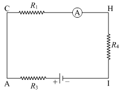
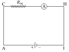
(ii) Both S1 and S2 are open. The circuit for this case is shown below. Here, R1, R4 and R3 are in series. Therefore, the equivalent resistance of the circuit is Req=R1+R3+R4 Hence, the current flowing in the circuit is I= \(\frac{V}{R_(eq)}\) = \(\frac{V}{R_1+R_3+R_4}\) where, V is the potential difference of the battery.
(iii) S1 is closed but S2 is open.
The circuit for this case is shown below. Here, R1 and R2 are in parallel. Their effective resistance is Now, R3, R' and R4 are in series. Thus, the equivalent resistance of the circuit is = \(\frac{R_1 R_2 +R_3 R_1 + R_3 R_2 + R_4 R_1 +R_4 R_2}{R_1+R_2}\) Hence, the current flowing in the circuit is = \(\frac{V(R_1+R_2)}{R_1 R_2 +R_3 R_1 + R_3 R_2 + R_4 R_1 +R_4 R_2}\) where, V is the potential difference of the battery.
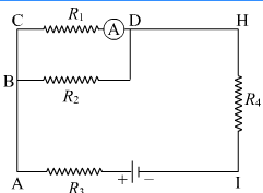
R'=\(\frac{R_1×R_2}{R_1+R_2}\)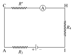
Req= \(\frac{R_1×R_2}{R_1+R_2} + R_3 + R_4 \)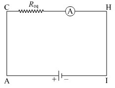
I=V/Req= \(\frac{v}{\frac{R_1 R_2 +R_3 R_1 + R_3 R_2 + R_4 R_1 +R_4 R_2}{R_1+R_2}}\)
Question 8:
Three resistances x1 , x2 and x3 are connected in a circuit in different ways. x is the effective resistance. The properties observed for these different ways of connecting x1 , x2 and x3 are given below. Write the way in which they are connected in each case. (I-current, V potential difference, x-effective resistance)
1. Current I flows through x1, x2 and x3
2. x is larger than x1 , x2and x3
3. x is smaller than x1, x2 and x3
4. The potential difference across x1, x2 and x3 is the same
5. x = x1 + x2 + x3
6. x = \(\frac{1}{\frac{1}{x_1}+\frac{1}{x_2}+\frac{1}{x_3}}\)
1. In this case, x1,x2 and x3 are connected in series. 2. In this case, x1 , x2 and x3 are connected in series. 3. In this case, x1 , x2 and x3 are connected in parallel. 4. In this case, x1 , x2 and x3 are connected in parallel. 5. In this case, x1 , x2 and x3 are connected in series. 6. In this case, x1 , x2 and x3 are connected in parallel.
Question 9:
Solve the following problems.
1. The resistance of a 1 m long nichrome wire is 6 Ω. If we reduce the length of the wire to 70 cm. what will its resistance be?
Resistance of a wire is directly proportional to its length. Let R1 and R2 be the resistances of the nichrome wire at 100 cm (1 m) and 70 cm, respectively. We know R= ρ(L/A) ∴ R1= ρ (L1/A) .....(i) and R2 =ρ (L2/A) .....(ii) Dividing (ii) by (i), we get R2/R1 = L2/L1 = 70/100 ⇒ R2 = (70/100) × R1 Now, R1 = 6 Ω ⇒R2=(70/100)×6 = 0.7 x 6 = 4.2 Ω
Required Resistance = 4.2 Ω
2. When two resistors are connected in series, their effective resistance is 80 Ω. When they are connected in parallel, their effective resistance is 20 Ω. What are the values of the two resistances?
Let the two resistances be R1 and R2. Therefore, ⇒R1R2=20(R1+R2) As, R1=80−R2 ⇒(80−R2)R2=20(80 −R2+R2) 80R2−R22=1600 R22−80R2+1600=0 (R2−40)(R2−40)=0 ⇒R2=40 Ω From (i), we get R1=80−40=40 Ω R1=40 Ω and R2=40 Ω
R1 + R2 = 80 Ω
or, R1 = 80 −R2-R2 .....(i)
and
1/R1+1/R2=1/20
3. If a charge of 420 C flows through a conducting wire in 5 minutes what is the value of the current?3.
Current flowing through the conducting wire is I= Charge(Q)/Time (t) ⇒I=420/(5×60)=420/300=1.4 A Hence, the current flowing through the wire is 1.4 A.